T914 Extended Fixed Filter Bank


Introduction:

And yes - another Moog filter is cloned, the 914 Extended Fixed Filter Bank. Other synthesizer concepts call them Formant Filter, but anyway - these filters don't have any voltage control but attenuate or emphasize the signal content concerning a certain frequency band by manual control (potentiometer).

The T914 consists like the original 914 of 14 filter bands. There are a low pass filter, 12 band pass filters and a high pass filter. The center frequencies of the band pass filters are: The behviour of the module is non-linear. If you process a square wave signal and enable all filter bands the output is no square but something complex with peaks and notches on the scope and it sounds much more "vivid" than the input does.

Circuit:

Again something for science fairs or boy scouts, as no capacity value of any filter stage exists in the circuit diagrams of Moog. The documents just say 'selected'.

So see below my list of capacity values I worked with:

Frequency HzC1C2
Low1u1u
125680n570n (470n + 100n)
175377n (330n + 47n)470n
250288n (220n + 68n)330n
350220n253n (220n + 33n)
500150n150n
700100n115n (100n + 15n)
100072n7 (68n + 4n7)68n
140047n62n (47n + 15n)
200038n6 (33 + 5n6)35n2 (33n + 2n2)
280022n26n7 (22n + 4n7)
400016n8 (15n + 1n8)19n7 (15n + 4n7)
560012n2 (10n + 2n2)15n
High1n51n5
Please refer to the original circuit for L-values or see the LTSpice circuit diagrams below for all component values.

Service: If requested I can provide sets of inductors / coils. Please send a mail request (mail address see below).

Schemas: Attention: Clicking a schema means acceptance of disclaimer on page bottom! It is the simple architecture of input - processing - output. The input signal passes the input buffer around Q1 (amplification factor 1) and is processed by the following 14 parallel filters of the filter stage. The result is amplified by the 3 stage output buffer (Q2, Q3 and Q4, amplification factor 70) to gain the same amplitude as the input signal.
The low pass filter circuit consists of two cascaded 2nd order passive LRC low pass filters with a total slew rate of 24db / oct. The band pass filter looks like a dual coupled RLC band pass, but with a resistor as the coupling element. I didn't find any background information about it, but it works fine :-)
The high pass filter circuit is a concatenated architecture as the low pass filter, just inverse, also with 24db / oct slew rate I suppose. R2 can be ommitted.

Part replacements:

I tried to build my module as close to the original as possible, but I had to do some changes due to actual components I use instead of the originals: Circuit changes:

After my LTSpice analysis of the original circuit I changed some parts of the output buffer for my T914 clone. Well, to be honest, I analyzed the circuit with the new transistor types listed above because my aim was to build the module without vintage components (transistors) of course, so the circuit was not really 'original', but quite close.
After building the circuit in reality I changed some more things within the output buffer because the module worked slightly different compared to the simulation. So at the end I had changed the following component values: Frontend:

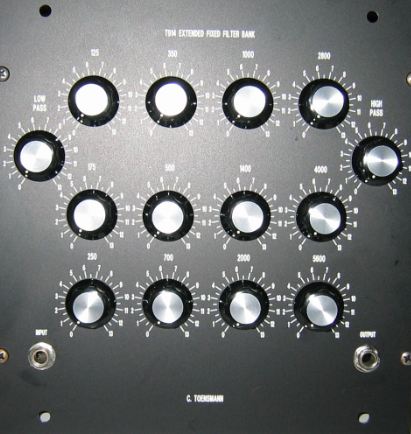
The human interface of the 914 shows one of the most characteristic module frontends I've ever seen. For me this frontend is one of the identifying elements of Moog modular systems - you see just this one, and you know: this is a Moog modular system, before you even had a look at the other modules.

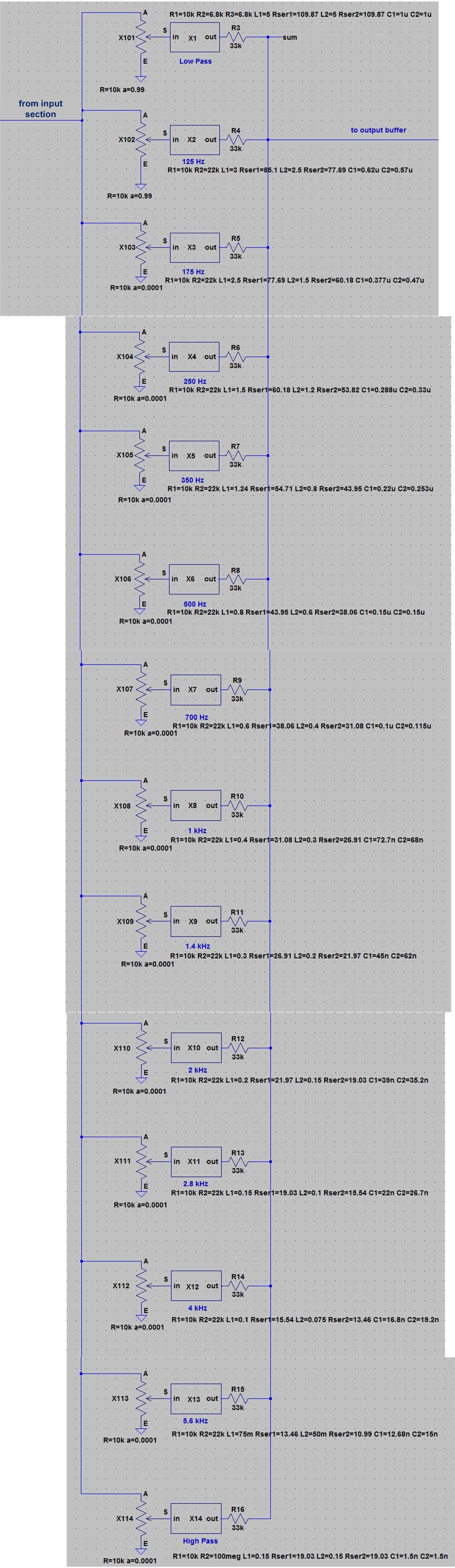
A lot of knobs - arranged in a kind of face look - are reponsible for one frequency band each (see list above). They are not only attenuating a frequency band but also emphasizing it.
Two connectors - one for input, one for output are the interface to the system. No backside connectors this time.


Board of the T914:


Click to enlarge

Click to enlarge

Click to enlarge

Click to enlarge

Click to enlarge


Complete module:


Click to enlarge

Click to enlarge

Click to enlarge

Click to enlarge


Sound example

Please send questions or remarks to:
Carsten Toensmann

Home


Disclaimer:
No warranty for completeness or correctness of technical descriptions, schemas or any information provided on www.analog-monster.de/* pages.
Contents of linked pages are in responsibility of the page owners and analog-monster dissociates from them.
All tracks provided on www.analog-monster.de/* pages is in ownership of www.analog.monster.de (except especially marked) and for private use only. All rights reserved.